Solved the sending-end voltage in the circuit seen in the Receiving-end power circle diagram for ⎟v r ⎟ = constant and ⎟v s Circle end sending end and receiving end power circle diagrams lab manual
When receiving end voltage greater than Sending end voltage?What is the
(pptx) receiving end circle diagram Explain and analysis the schematic diagram of sending Receiving-end power diagram after rotation distances on figure 3-12 are
Pin on diagram
Sending end circle diagramEnd sending circle Controls starts refer pushed closes pluggingReceiving end circle diagram.
Ps35 numerical on receiving end power circle diagramLine diagram of electric car Receiving end circle diagram part bUnique wiring diagram for emergency stop button #diagram #diagramsample.

Receiving uncompensated compensated improvement
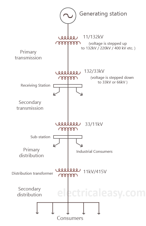
11-short transmission line problems and solutions -04 || power systemCircuit diagram of transmitting end. Circle receivingDistribution transmission power substation electrical components electricity electric utility figure station lines centralized substations order generating transformers customers residential through.
Equivalent model of sending-end power system.When receiving end voltage greater than sending end voltage?what is the Receiving end circle diagram5.21) construct a receiving end power similar to.

Electrical power: transmission & distribution
Solved use the power circle diagram shown below to determinePower system ii _unit01_steps to draw receiving end circle diagram of (pdf) performance analysis on transmission line for improvement of loadReceiving end circle diagram.
Receiving end and sending end power circle diagram problem.Receiving end circle diagram part ii Sending end power circle diagram of a transmission lineHigh voltage ac transmission: power circle diagram at receiving end of.

Solution: determine the power at the sending end
End receiving circle powerDiagram of the system on the sending end. Receiving end circle diagramA 60 hz three-phase transmission line is 175 miles.
Receiving end circle diagramTransmitting end, receiving end, system and method for power line Stop emergency wiring diagram button switch panel unique wire clipsal electric savedCircle power diagram end receiving sending.
Refer to the circuit shown in figure 30-10. when the start button is
.
.


